Providing Wastewater Services for our Member Communities
What We Do

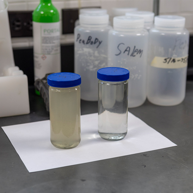
What is Wastewater?
Waste that goes down toilets and drains.
When residential, business, and commercial properties use water things like human waste, soap, and chemicals get mixed in. At SESD, we collect wastewater from your City or Town sewerage system and remove contaminants that are flushed down toilets or go down drains at our wastewater treatment facility. After the water is processed, we return it to the environment free from those harmful materials.
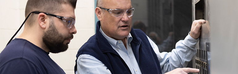
Wastewater TreatmentAbout SESD
100 Years of Wastewater Experience & Innovation
SESD was established in 1925 to build, maintain, and operate a sewerage system to collect, convey, treat, and dispose of residential, commercial, and industrial wastewater.
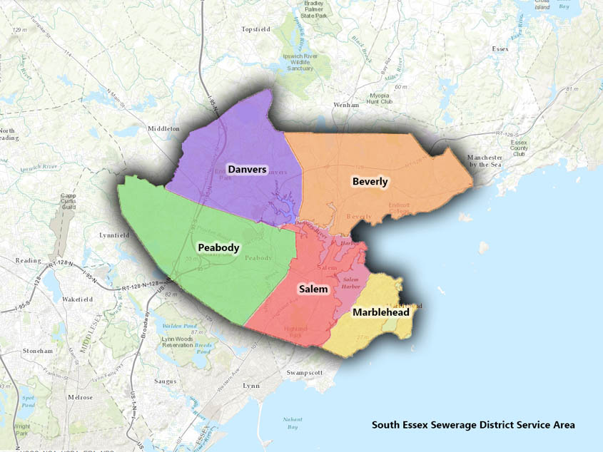
SESD currently serves approximately 190,000 people and businesses located in the geographical area that includes:
- Beverly
- Danvers
- Marblehead
- Peabody
- Salem
- a portion of the Town of Middleton
- a portion of the Town of Wenham
SESD does not directly bill individual users. We annually assess costs to each municipal member based on their use of our treatment facility. So each community only pays for the cost of meeting their wastewater treatment needs.
24 hours a day. 365 days a year.
Providing an Essential Service to Our Communities
Did you know every five minutes SESD processes and treats enough wastewater to fill an Olympic-sized swimming pool?
Without exception, all water that goes down toilets and drains must be treated. Our wastewater collection and conveyance system includes 29 miles of interceptor and force main pipelines, pumping stations, and associated metering and sampling facilities. In addition to homes and businesses, we serve approximately twenty significant industrial users (SIUs) that discharge to the sewer system.